

LV Node
TRANSFORMER STATION MEASUREMENTS
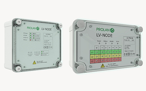
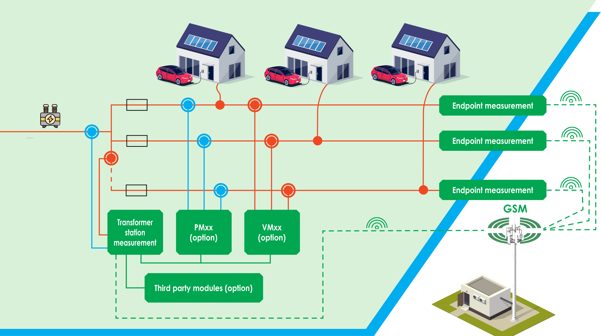
The LV-PA34 device performs supply-point measurements on the secondary side of the MV/LV transformer and transmits the data via a communications modem to the data center. Supply-point measurement involves measuring three voltages and three (or optionally four) currents. In addition to generating its own measurement data, the LV-PA34 can communicate with further proprietary or third-party devices and transmit their data as well.
TRANSFORMER STATION BRANCHING MEASUREMENTS
The LV-NODE product family's supply-point central unit, the LV-PA34, can be expanded with additional Prolan-manufactured plug & play expansion modules. This solution makes it possible to monitor multiple branches originating from a single transformer without installing multiple modem-equipped units. The LV-PMxx devices measure branches current and power, while the LV-VMxx devices check for voltage presence.
END-POINT MEASUREMENTS
Within the LV-NODE product family, the LV-VA3 device is the modem-equipped option for voltage measurement at line endpoints. Its feature set is similar to the LV-VA34, but given its intended installation environment, it cannot be expanded with additional modules and does not measure current. As a result, it has a much simpler, more efficient design and installation process.
MAIN FEATURES
- Power quality measurements according to EN 50160, EN 61000-4-30, and EN 61000-4-15
- Voltage measurement accuracy of 0.5%, current measurement accuracy as low as below 1%
- Three-phase voltage measurement with an internal fuse
- Three-phase (optionally four-wire) current measurement using a Rogowski sensor
- Changeable current sensors with IP65 connectors
- LTE 4G communication with either an integrated or external antenna, depending on the model
- Optional GPS location and time synchronization
- Support for multiple IoT protocols (e.g. MQTT, Microsoft Azure)
- Remote configuration and firmware updates
- Up to five minutes continuous measurement and communication in case of power failure
- Operation from a single active phase if needed
- LED status indicators on the device front panel
- UV-resistant, IP65-rated enclosure
- Installation without opening the device enclosure
- Live installation possible (no power shutdown required)
MEASUREMENTS
Periodically Generated Data (Statistics):
- Average, minimum, and maximum for each measured quantity
- Configurable cycle time in minute resolution
- Voltage and current RMS
- Active, reactive, and apparent power
- Power factor
- Voltage and current THD
- Individual voltage and current harmonics
- Voltage and current asymmetry
- Mains frequency
Events, Alarms:
- Voltage dip
- Voltage swells
- Rapid voltage changes
- Overcurrent
- Voltage interruptions
- Medium-voltage line break
- Door opening
Other Data:
- Flicker Pst1 and Pst10
| Operating voltage range | 100…280 VAC |
| Power consumption | 3 W (average), max. 5 W |
| Operating temperature | -20…70 °C |
| Voltage measurement | 3-phase |
| Voltage measurement accuracy | ≤0.5% |
| Voltage measurement range | 0…280 VAC |
| Voltage measurement overload capability | 440 VAC (1 minute) |
| Internal fuse | 6.3 × 32 mm, 2A, 500V, I1 ≥ 20 kA |
| Current measurement | Rogowski sensor |
| Current measurement accuracy | ≤1% |
| Current measurement range | 30…3000 A |
| Trip threshold for current measurement | max. 2 A |
| Current measurement overload capability | 20 kA |
| Impulse withstand voltage | 6 kV |
| Insulation strength | 2.5 kVeff |
| Power supply holdup time | 5 minutes |
| Module power supply | From network through voltage measurement |
| Sampling frequency | 32 kHz |
| Internal clock accuracy | <1 s/day |
| Remote communication | LTE 4G, GPRS |
| Communication protocols | MQTT, MS Azure IoT Hub, Mender.io, NTP |
| Local communication | 2 × RS485 |
| IP protection | IP65 |
| Mounting | With screws or band clamp (max. 18 mm width) |
-(3)-thumb.jpg)
-(2)-thumb.jpg)
-(1)-thumb.jpg)

-(1920-x-1080-képpont).png)
-(3).png)
-(2).png)
-(1).png)